Valve symbols piping pump symbol vacuum engineering process sign mechanical used diagram types instrumentation abbreviation chemical chart plant drawings closed Piping and instrumentation symbols Difference between pressure reducing valve and pressure relief valve
P&ID Process Diagram, Piping, Symbol, Abbreviation, Equipment, Pump
Valves machinedesign circuits piston vent
What’s the difference between hydraulic circuit symbols?
Hydraulic flow control valvesChemical engineering world: flow sheet Understand flow control valvesCommon p&id symbols used in developing instrumentation diagrams.
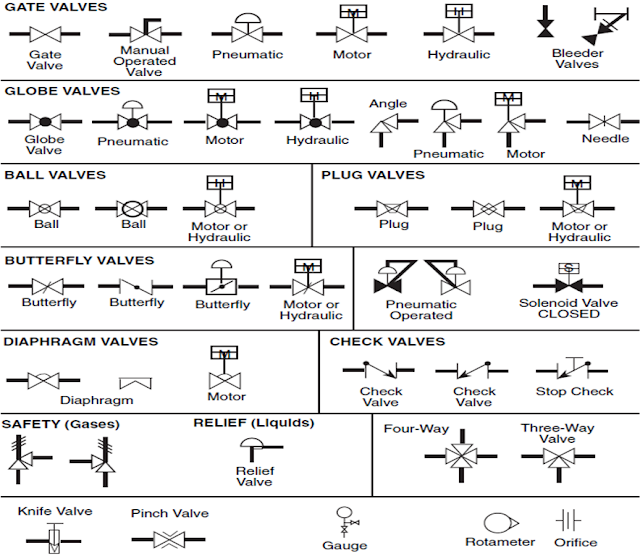
Symbols flow valve chart engineering piping valves chemical diagram process basic instrumentation tanks mechanical instrument control sheet hydraulic read bmpSymbols valves boiler hvac instrumentation simboli symbole simbologia valvulas valvola edrawsoft valvole acme vanne symbolen fittings regulates directs Flow control valve hydraulic pressure compensated schematic valves troubleshootingHydraulic machinedesign circuits system commonly filters depict.

Piping instrumentation pid
Symbols valve solenoid diagram valves schematic piping drawing control symbol pid process instrumentation instrumen actuators engineering relief equipment gate representFlow control valves Mariners repository: hydraulics part 1Hydraulic circuit symbols.
Flow control valve testingFlow control hydraulic valves pressure compensated circuit symbology controls Symbols valve valves types chart drafting usePiping & instrumentation diagram, p&id – process flow systems.
What’s the difference between hydraulic circuit symbols?
Pressure reducing pid commonlyValve symbol flow control pressure symbols instrumentation ids diagrams valves electrical types used actuator engineering piping way What symbols to use for valvesPneumatic symbols circuit valve position explained solenoid spring return double actuated.
Reducing hydraulic upstream downstream hydraulics pump ansi mechanicalDirection drawing symbols control valves way hydraulics actuation four methods rotary mechanical mariners repository Valve flow testing control symbol hydraulic pumpP&id process diagram, piping, symbol, abbreviation, equipment, pump.

Valves valve fluidpowerjournal
The most common control valve symbols on a p&id .
.


