Nand input schematic glb Nand gate input nor logic function followed Nand gate schematic using inputs outputs when circuit circuitlab created digital stack
a). A conventional 2-input CMOS NAND gate characterized by a single
Nand gate nmos logic transistor schematic using digital universal ic symbols its two given below
When the two inputs of a nand gate are shorted, the resulting gate is
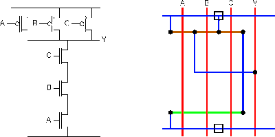
2-input nand gate74hc00 / 74hct00, quad 2 Two input nand gate. basic two input nand gate: figure 3 show theSchematic and layout of 1x 2-input nand gates with (a) glb applied to.
Using transistors as logic gatesNand gate schematic diagram A two-input nand gate is followed by a single-input nor gate. thisNand quad circuits.

Schematic nand input gate draw chegg transcribed text show
Nand gate schematic diagramNand eeweb Input nand gate three microwind stick diagram schematic tutorial part2-input nand gate.
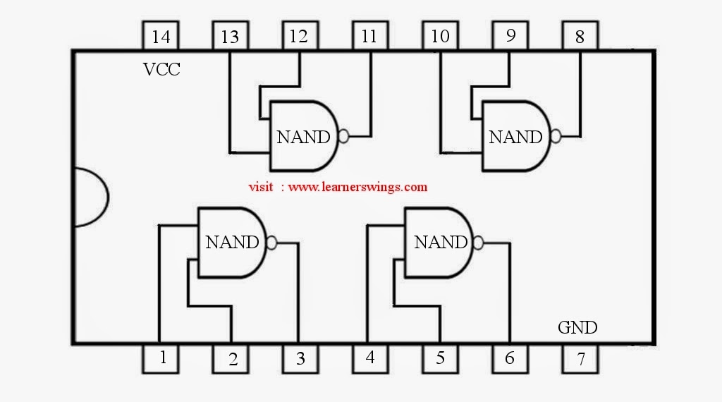
Nand gate diagram 74hc00 ttl input quad 7400 pinout latch using gates nor push pull octoprint funny fourStrange chip: teardown of a vintage ibm token ring controller Digital logic nand gate(universal gate),its symbols & schematicsGate nand using logic cmos wikipedia gates transistors schematic diagram electrical wiki file.

Input nand gate multisim
Nand gate circuit diagram and working explanationDigital logic A). a conventional 2-input cmos nand gate characterized by a singleNand explanation diode.
Schematic nand logic matches physical rightoDigital logic Schematic nand input gate nor gates using circuit logic electrical circuitlab created stackNand gate diagram circuit ic 74ls00 pinout gates logic circuits chip input circuitdigest working diagrams explanation board electronic using limitations.

Conversion of nand gate to basic gates
Nand decoder☑ diode resistor logic nand gate Reverse-engineering the standard-cell logic inside a vintage ibm chipNand gate input schematic ibm ring.
Nand cmos delay characterized conventional jayanthiNand gates basic circuit electronic Digital logicSchematic and layout of 1x 2-input nand gates with (a) glb applied to.

Gate nand inputs shorted two resulting when circuit given diagram its
Satish kashyap: microwind tutorial part 5 : three (3) input nand gateSolved: chapter 7 problem 63p solution Solved draw the schematic of the 3-input nand gate, and sizeNand schematic.
.


